The Hidden Variables That Determine Long-Range Antenna Performance in the Field
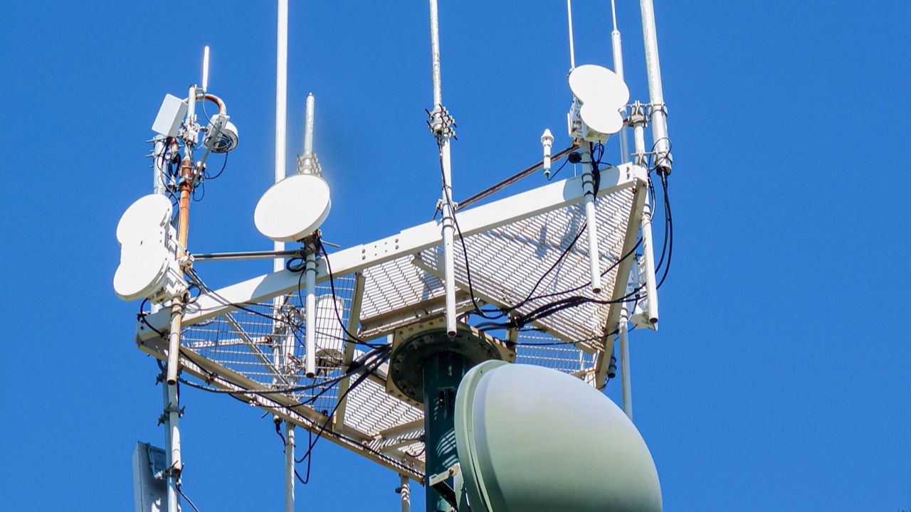
Antenna datasheets are useful documents. They tell you gain, radiation pattern, VSWR, frequency range, connector type. For most purchasing decisions, that’s enough information to make a reasonable choice. But when a long-range link underperforms its predicted capability in the field, the explanation is almost never in the datasheet. It’s in the variables the datasheet doesn’t measure — and in some cases, can’t.
I’ve spent a fair amount of time on long-range wireless link evaluations, and the failures that take the longest to diagnose are never the obvious ones. It’s not the wrong frequency or the backward connector. It’s the subtler physics that shows up only when you’re trying to squeeze the last few kilometers out of a link and it refuses to cooperate.
Fresnel Zone Clearance — the One That Surprises Engineers Most
Line of sight is not the same as radio line of sight. Two antennas pointed at each other across a field with nothing visibly blocking the path between them can still be operating in a partially obstructed RF environment, because radio waves don’t travel in infinitely thin lines.
Radio propagation occupies an ellipsoidal volume around the direct path between transmitter and receiver, called the Fresnel zone. The first Fresnel zone is the region that contains the most energy-significant portion of the wave. Any obstruction that intersects this zone — a hill that clears the visible line of sight by only a meter, a tree line, a building rooftop — diffracts energy away from the receiver path and reduces received signal strength.
The radius of the first Fresnel zone at the midpoint of a link depends on frequency and path length. At 868 MHz over a 5km path, the midpoint Fresnel radius is roughly 15 meters. That means an obstruction needs to clear the direct path by 15 meters at the midpoint — not just the geometric line — to avoid Fresnel zone losses. Closer obstructions at shorter path lengths have smaller zones, but the zone still exists and still matters.
Most link budget calculations treat terrain and obstructions as binary — clear line of sight or not — and miss partial Fresnel zone obstruction entirely. It’s one of the most common explanations for why a link that should work at 10km only reaches 6km in practice.
Antenna Elevation Pattern Tilt
Antenna datasheets show the radiation pattern as a polar diagram, usually in both the azimuth (horizontal) and elevation planes. What the diagram often obscures is the exact elevation of the maximum gain beam — and this matters for long-range links where the geometry between antennas is not perfectly horizontal.
A vertically polarized omnidirectional antenna has maximum gain in the horizontal plane. In free space theory, this is the 0-degree elevation plane. In practice, ground proximity shifts the effective elevation pattern — an antenna mounted close to the ground can have its maximum radiation angle tilted upward or downward by a few degrees depending on mounting height and ground conductivity. For distant targets at low elevation angles, a downward tilt of even 2 to 3 degrees translates to a meaningful gain reduction.
Directional antennas compound this effect. A panel or Yagi antenna that’s physically aimed “at” a distant target may not be correctly aimed at it in the elevation plane if the calculation didn’t account for the height difference between the two endpoints and the terrain profile between them. A long-range link where one endpoint is significantly higher than the other needs the antenna elevation angle to account for this geometry explicitly.
Using a properly specified long range antenna addresses part of this problem, but even a high-quality antenna underperforms if it’s aimed incorrectly in elevation.
Temperature Effects on Feedline Loss
Coaxial cable attenuation increases with temperature. This is a physical property of cable that’s predictable and well-characterized, but rarely factored into field deployments where the cable runs through environments with significant temperature variation.
Standard RG58 cable rated at a certain loss per meter at 20°C will have noticeably higher attenuation at 50°C — the kind of temperatures a cable run across a roof in summer can see. For a short cable run, the effect is small. For a 30-meter cable run on an elevated mast in full sun, it starts to matter, particularly for links that are already operating near their sensitivity margin.
The practical consequence is that a link that works reliably in winter may start having intermittent issues in summer, with the degradation appearing gradually over the course of a warm day and recovering overnight. This thermal performance pattern is frequently attributed to “interference” or “atmospheric conditions” when the actual cause is cable attenuation increasing as the installation heats up.
Low-loss cable types (LMR-400 and similar) have lower temperature sensitivity than standard coaxial cable, which is another argument for using them on long-run outdoor installations even when the loss difference at baseline temperature seems manageable.
Connector and Weatherproofing Losses Over Time
New connectors have low insertion loss — typically 0.1 to 0.3 dB per connector depending on type and quality. This is small enough to ignore in most link budgets. Weathered outdoor connectors are different.
Water ingress into an SMA or N-connector accelerates oxidation of the center pin and the mating surfaces. Even partial oxidation increases contact resistance, and contact resistance increases insertion loss. A connector that was 0.2 dB at installation may be 1 to 2 dB after two years of outdoor exposure without adequate weatherproofing — a loss increase that can close a marginal long-range link.
Self-amalgamating tape over outdoor connector joints is standard practice for a reason. Failing to apply it, or applying it improperly so moisture still reaches the connector interface, is a latent failure mode that doesn’t show up on day one of deployment but shows up reliably over time.
The cumulative effect of even minor degradation at multiple connectors along a cable run — feedline to antenna, feedline to radio, any inline adapters — adds up. A system that has four outdoor connectors, each degraded by 0.5 dB from weathering, has 2 dB of invisible link budget erosion that was not present at commissioning.
What Field Testing Actually Reveals
The variables above share a common characteristic: none of them are visible in a bench test or a datasheet comparison. They only appear when the hardware is deployed at operational height, in the target environment, across the intended path, under realistic temperature and weather conditions.
For links where range performance matters, field testing with calibrated signal strength measurement at multiple known distances — not just “does it work or not” — gives the input needed to separate the theoretical link budget from the real-world performance margin. The gap between them is where these variables live.